Sequential course of optimization for a digital mild processing system to reduce trial and error
[ad_1]
Single-layer take a look at
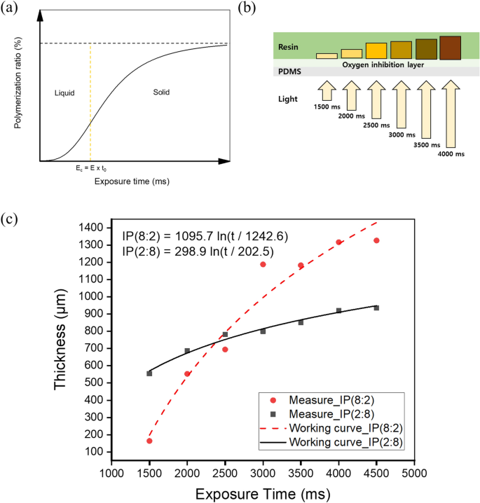
The cured thickness of the resin as a result of photopolymerization response may be calculated and predicted mathematically. When UV mild hits the resin, some mild is scattered or absorbed on the resin floor. Based on the Beer–Lambert regulation, the depth of sunshine decreases exponentially. Equation (1) is the working curve equation, which is derived by arranging the publicity equation obtained by the Beer–Lambert regulation by way of power, the place Cd is the utmost curing thickness, Dp is the penetration depth of sunshine, Emax is the utmost publicity power of the resin floor, and Ec is the essential power at which the resin part adjustments right into a stable. As proven in Fig. 4a, the essential power Ec is the minimal power required to provoke photopolymerization. Based on Eq. (1), the curing properties of resins rely on two parameters: publicity power and penetration depth43,44. As the quantity of power enter and penetration depth improve, the cured thickness of the resin will increase.
$${C}_{d}={D}_{p},mathrm{ln}left[frac{{E}_{max}}{{E}_{c}}right]$$
(1)
$${C}_{d}={D}_{p},mathrm{ln}left[frac{Ecdot t}{Ecdot {t}_{0}}right] = {D}_{p},mathrm{ln}left[frac{t}{{t}_{0}}right]$$
(2)
Based mostly on Eq. (2), the curing thickness of the resin may be predicted utilizing the publicity time as a course of variable, the place t is the publicity time, t0 is the essential time. As proven in Fig. 4b, the construct plate was eliminated, and two forms of newly developed resins had been positioned on the PDMS-coated vat. A sq. sample of two × 2 mm2 was uncovered to every resin with a light-weight supply with a wavelength of 405 nm from 1500 to 4500 ms at intervals of 500 ms. Based on Eq. (1), the depth of penetrated UV mild is proportional to the publicity time, as a result of the utmost publicity power is determined by the time integral of the irradiance. To guage the thickness of the cured single layer in line with numerous publicity occasions of UV mild, the cured single layer was separated from the vat, washed with isopropyl alcohol (IPA), and the cured thickness was measured utilizing an optical microscope (MS-12Z-L1215).
The curing thickness in line with the publicity time of the 2 forms of resins is proven in Fig. 4c. The curing thickness is managed by including a particular dye, photoinitiator, or UV absorber to the photocurable resin. Nonetheless, on this case, decreasing the transparency of the uncooked materials is disadvantageous. Thus, the publicity power was used to keep up the transparency of the photocurable resin.
The essential power Ec is obtained by multiplying the essential time t0 and the illuminance E41. Ec is troublesome to watch experimentally. It’s because, in idea, the curing thickness is zero at Ec. Due to this fact, prediction is a regular technique for deriving Ec45. A bent line was obtained from the measured curing thickness, and the corresponding x-intercept worth was assumed to be t0. The typical mild penetration depth Dp was obtained by substituting the measured Cd, t0, and t values into Eq. (2). Consequently, the working curve equation of the resin was derived, as proven in Fig. 4c. Extra experiments had been carried out to confirm the derived working curve equation, as proven in Fig. S8. The cured thickness is extremely delicate to publicity time with a considerable amount of ISDM. As proven in Fig. 4c, IP(2:8) had a significantly decrease gradient than IP(8:2). It’s because the photopolymerization ranges of the ISDM and PTMG PUA differ in line with the publicity power. This consequence signifies that IP(8:2) permits a broader vary of thickness management.
Resin recoating take a look at
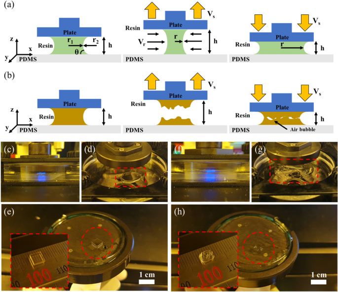
After one layer is fabricated within the DLP system, the construct plate rises farther than the layer thickness within the z-axis course, as proven in Fig. 5a. After the z-axis has stopped and a set delay time had handed, the construct plate was lowered to the following layer place. On this course of, resin settling conduct happens. As such, the success of recoating is decided by the photocurable resin viscosity and the construct plate pace.
Habits of (a) low-viscosity resin and (b) high-viscosity resin in line with the motion of the construct plate within the z-axis course. (c,d) Photopolymerization and non-breaking resin interface of low-viscosity resin. (e) Samples with out inner bubbles and form errors resulting from secure recoating. (f g) Photopolymerization and breaking resin interface of high-viscosity resin. (h) Pattern form error resulting from poor recoating.
In a DLP system, the viscosity of the photocurable resin is a vital parameter46,47. The upper the viscosity of the resin, the extra time is required for recoating, and the opportunity of air bubbles within the fabrication space will increase, as depicted in Fig. 5b.
The vat coated with PDMS was positioned above the optical system, and a glass construct plate was mounted on the z-axis stage and positioned parallel to the vat (Fig. 1a). Assuming that the vat and the construct plate are parallel, the photocurable resin flows between infinitely massive plates with very slender gaps. Due to this fact, the resin move between the vat and construct plate may be assumed to be a completely developed laminar move with out time disturbance48. The capillary pressure dominates the pressure appearing on the 2 plates and the resin as a result of the impact of gravity is negligible for liquids between the micro/nanogap. A big adverse stress is generated on the liquid interface between the 2 plates at micro/nano spacing, which capabilities as a big adhesion pressure between the 2 plates49,50.
The adhesion between the construct plate and vat is a essential issue to think about for profitable fabrication in a bottom-up DLP system. The preliminary situation setting contemplating the adhesive pressure was managed within the following sequence. The present sequence conformed to the recoating situation in line with the conduct of the resin between the 2 plates.
The recoating course of proceeded within the DLP system, as proven in Fig. 5a,b. Determine 5a illustrates using a resin with an applicable viscosity, and Fig. 5b illustrates using a high-viscosity resin. The interior stress of the resin between the vat and construct plate is expressed by Eq. (3):
$$Delta p=Tleft(frac{1}{{r}_{1}}-frac{1}{{r}_{2}}proper)$$
(3)
the place T is the floor rigidity, r1 is the radius of the center level between the vat and the construct plate contained in the resin, and r2 is the radius of curvature exterior the resin. When the stress contained in the droplet is decrease than the surface stress (Δp < 0), the capillary adhesion pulls the 2 surfaces above and beneath. The generated capillary adhesive pressure is expressed by Eq. (4).
$$F=frac{2TVmathrm{cos},theta }{{h}^{2}}$$
(4)
the place V is the quantity of the resin, θ is the contact angle, and h is the space between the vat and the construct plate. Assuming that the quantity of evaporation of the resin is negligible, the numerator may be handled as a continuing. Due to this fact, adhesion is most affected by the hole between the vat and construct plate, and adhesion F decreases because the construct plate rises51.
Assuming that the floor roughness of the vat and construct plate is uniform when the construct plate rises, the interface retreats within the radial course of the construct plate to keep up the resin quantity and call angle on the floor52,53, as depicted in Fig. 5a. The resin is recoated due to this move, however the fingering impact and bubbles happen as a result of instability of the interface relying on the viscosity of the resin54.
In a low-viscosity resin, the interface stability of resin-vat and resin-build plates is excessive as a result of the move price Vr of the resin is larger than or equal to the speed of improve of the construct plate pace Vs. Accordingly, the motion of the resin and the construct plate has excessive synchronicity, as depicted in Fig. 5a. Nonetheless, for a high-viscosity resin, as a result of Vr is smaller than Vs, there’s a mismatch within the resin motion for the construct plate motion, inflicting the resin to separate, as depicted in Fig. 5b. This causes bubbles within the resin and fabrication failure.
Owing to the quick fabrication pace of the DLP system, the photocurable resin ought to behave flexibly between the vat and construct plate. The resin move between the 2 plates is an incompressible laminar move, and the speed distribution Vr of the resin is expressed by Eq. (5)55:
$${v}_{r}=frac{zDelta p}{mu L}left(h-zright)$$
(5)
the place z is the vertical distance from the vat, L is the x-direction size of the curing space, and μ is the viscosity of the resin. The utmost velocity Vmax happens at level h/2, and is expressed by Eq. (6):
$${v}_{max}=frac{Delta p{h}^{2}}{4mu L}$$
(6)
As beforehand talked about, the flexibleness of the resin move in the course of the rise and fall of the construct plate is essential for efficient recoating. Accordingly, a distinction between the construct plate pace Vs and the resin pace Vmax nearer to 0 is perfect. When the construct plate motion time is tb, the pace Vs may be expressed as h/tb. If that is summarized for time tb along with Eqs. (6), (7) is an identical.
$${t}_{b}=frac{4mu L}{Delta ph}$$
(7)
Based on Eq. (7), the upper the viscosity of the resin, the extra time is required for the construct plate motion. Due to this fact, using a low-viscosity resin is advantageous for speedy manufacturing and secure recoating in a DLP system. The connection between the construct plate pace and viscosity additionally impacts the construct space, but it surely was not thought of on this research as a result of the utmost construct space was as small as 13 × 7.5 mm2.
The manufacturability based mostly on the distinction in viscosity was confirmed by experiments utilizing the low-viscosity IP(8:2) and high-viscosity IP(2:8) resins chosen on this research. A 5 × 5 × 1 mm3 pattern was fabricated with the DLP system, as proven in Fig. 5c,f beneath a layer thickness of 100 µm, z-lift distance of 1 mm, and z-lift pace of 100 mm/min. As a result of the aim of this experiment was to verify the impact of viscosity, the publicity time was set to 2500 ms such that the resin could possibly be sufficiently photopolymerized. The time required for the one-layer course of cycle beneath this situation was 5.9 s.
A definite distinction in resin conduct in line with viscosity was confirmed when the construct plate returned to its origin. The IP(8:2) resin maintained a mass on the vat with out breaking the interface in the course of the course of, as proven in Fig. 5d. The pattern in Fig. 5e was produced with out inner bubbles or form errors.
In distinction, within the IP(2:8) resin, as proven in Fig. 5g, the interface was damaged on the vat and separated, inflicting air bubbles in the course of the course of, interfering with resin filling, and inflicting manufacturing defects, as proven in Fig. 5h. For top-viscosity IP(2:8) resin, the outcomes may be improved if the z-lift pace is lowered and adequate recoating time is taken into account. Nonetheless, this requires a really lengthy course of time, which limits the quick manufacturing of the DLP system. Due to this fact, IP(2:8) resin was not thought of within the subsequent sequence, and optimization was carried out utilizing IP(8:2) resin.
First layer adhesion take a look at
To reliably connect the primary layer to the construct plate, the adhesive pressure between the construct plate and the primary layer should be higher than the stress that happens when the construct plate is raised for the following layer. The pressure that happens when two plates are separated between a viscous fluid is outlined because the Stefan adhesion in Eq. (8)56,57:
$$F=frac{3pi mu {R}^{4}}{2{h}^{3}}frac{dh}{dt}$$
(8)
the place R is the radius of the separating plates, h is the space between the 2 plates, μ is the viscosity of the fluid, and dh/dt is the speed of separation. Equation (8) signifies that the pressure utilized to the earlier layer is linearly proportional to the separation pace because the construct plate strikes to the following layer. Beforehand, the connection between the processing time and resin viscosity at a z-lift pace of 100 mm/min was confirmed by the resin-recoating take a look at sequence. The z-lift pace of 100 mm/min was the identical as that of Eq. (8).
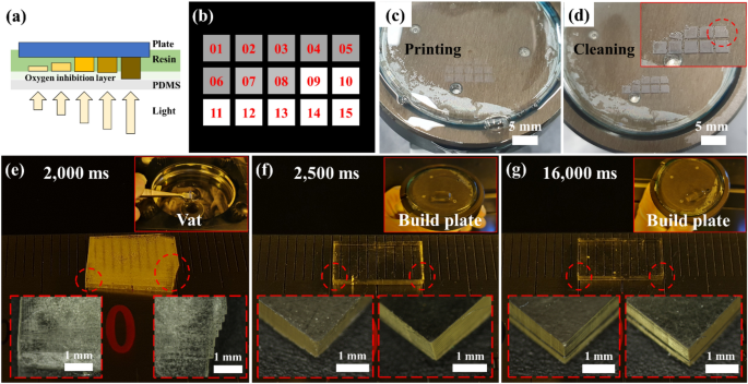
To establish the adhesion situation of the primary layer at a separation pace of 100 mm/min, 2 ml of IP(8:2) resin was positioned into the vat, as depicted in Fig. 6a, and the construct plate was set on the beginning place. Determine 6b illustrates {that a} 2 × 2 mm2 sq. picture was generated as a 3 × 5 array. Every picture was cured on the construct plate by sequential publicity to 405 nm mild from 1600 to 3000 ms at 100 ms intervals. After the method was accomplished, the construct plate was raised at a separation pace of 100 mm/min. The cured sample on the construct plate proven in Fig. 6c was washed with IPA, and a definite sample was noticed, as proven in Fig. 6d.
(a) Schematic diagram for the primary layer adhesion take a look at. (b) 3 × 5 sq. picture sample for adhesion take a look at in line with the publicity time. (c) First layer fabrication in line with the publicity time. (d) After cleansing the construct plate, the publicity time was confirmed to be appropriate for first layer adhesion. (e) Failure to construct plate adhesion resulting from inadequate publicity time. Misalignment of every layer is noticed. (f) Pattern fabricated by making use of the optimum first layer publicity time. (g) First layer with extreme publicity time utilized, inflicting dimensional accuracy failure and deformation resulting from step distinction.
The sample not hooked up to the construct plate and that remaining on the construct plate are confirmed in Fig. 6d. Patterns that don’t adhere to the construct plate are resulting from inadequate adhesion to withstand the stresses brought on by the separation pace. A secure adherence to the construct plate was achieved from the tenth sample, indicating that the primary layer required 2500 ms or longer publicity time.
A ten × 5 × 1 mm3 pattern was ready to verify whether or not the first-layer publicity circumstances had been applicable for the DLP system. Determine 6e illustrates the case of inadequate adhesion. The primary layer utilized the 2000 ms situation, and the remaining layers had been fabricated with a layer peak of 100 µm beneath the 1600 ms situation. Within the working curve of the single-layer take a look at, 2000 ms was a adequate time for photopolymerization. Nonetheless, the 2000 ms situation supplied inadequate power for construct plate adhesion; thus, the method was terminated with the pattern floating within the vat, as proven within the inset picture of Fig. 6e. Samples had been created as unaligned layers as a result of when the preliminary layer adhesion failed, extra layer fabrication brought about layer slip.
In Fig. 6f, 2500 ms derived by experimentation was utilized because the optimum first-layer situation, and the remaining layers had been fabricated with a layer peak of 100 µm beneath the 1600 ms situation. The pattern was fabricated in a state of adhesion to the construct plate, as depicted in Fig. 6f. Every layer of the pattern was aligned throughout fabrication. Lastly, in Fig. 6g, the primary layer situation was utilized at 16,000 ms, ten occasions the method situation (beneficial as the primary layer circumstances for industrial tools).
The pattern was adhered to a construct plate in the course of the fabrication. Nonetheless, as proven in Fig. 6g, a step distinction was noticed between the primary and subsequent layers, brought on by over-curing owing to the extreme publicity time of the primary layer. A step distinction impacts the dimensional accuracy and causes product deformation sooner or later. Due to this fact, confirming the first-layer adhesion situation utilizing the tactic proposed on this sequence is useful for profitable fabrication. The optimized publicity time of the primary layer adhesion for IP(8:2) was 2500 ms.
Over-cure take a look at
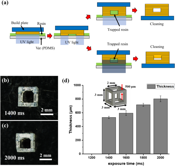
Fabricating overhang constructions utilizing the VPP technique stays difficult, notably when the highest angle is nearly parallel to the construct plate. As proven in Fig. 7a, the resin trapped within the construction causes a further photopolymerization response resulting from UV transmission, inflicting an over-curing drawback58. As the scale of the construction decreases, the within is clogged, and a sizeable dimensional error happens.
IP(8:2) resin with an acceptable viscosity for the DLP system was chosen based mostly on the resin recoating take a look at. Moreover, the primary layer adhesion take a look at carried out within the third sequence confirmed that the preliminary publicity situation for secure attachment to the construct plate was 2500 ms. Publicity time circumstances had been chosen by referring to the working curve of the primary sequence. The experiment was performed with publicity time circumstances set at 200-ms intervals from 1200 to 2000 ms. Within the 2000-ms situation, as much as 5 occasions the publicity power may be produced in contrast with the laminate thickness.
A 3 × 3 × 3 mm3 lattice construction with a line width of 500 μm was fabricated beneath the circumstances of a layer thickness of 100 μm, z-lift pace of 100 mm/min, and first-layer publicity time of 2500 ms. The fabricated lattice construction was washed with IPA and post-processed for 3 min in a UV oven with a wavelength of 405 nm. The thickness of the higher body of the manufactured lattice construction was measured utilizing an optical microscope (MS-12Z-L1215, SEIWA Optical), as proven in Fig. 7b,c.
The outcomes for every situation are proven in Fig. 7d. Below the 1200-ms situation, because the publicity power was inadequate to trigger a photopolymerization response, the fabrication was unsuccessful. In distinction, on the 2.000-ms situation, over-curing of as much as 1.6 occasions the design thickness of 500 μm occurred owing to extreme publicity power. Due to this fact, the optimum publicity time was 1400 ms, 5% of the design thickness was overcured, and this worth was the optimum overlap situation.
Nonetheless, beneath these course of circumstances, regardless of decreasing over-curing, the energy and sturdiness of the construction instantly after fabrication had been low as a result of the bonding pressure between every layer was weak. Thus, post-processing in a UV oven after IPA cleansing was important to enhance the low energy and sturdiness. UV curing additionally induced a whole response of the photoinitiator remaining on the structural floor. Due to this fact, UV curing improved energy and sturdiness and lowered the organic toxicity.
Analysis and software
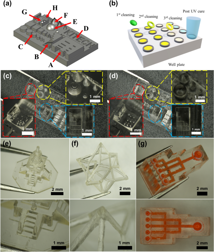
The optimum course of circumstances for the developed resin had been obtained by SPO, as beforehand described. The take a look at artifact for confirming manufacturability was designed to judge whether or not the obtained circumstances had been appropriate, as depicted in Fig. 8a. The take a look at artifact was divided into eight sections from A to H to verify manufacturability. Part A confirmed the manufacturability of the overhang construction in line with the x–y side ratio, and Part B evaluated the fabrication precision in line with the angle. The manufacturing of cylinders and sq. pillars in line with the x–y side ratio was verified in Part C. Part D confirmed the implementation of the engraved sample in line with the width, and part E evaluated the manufacturing precision of the spherical form. Part F evaluated the fabrication of the cone form in line with the angle, and part G confirmed the manufacturability of the cantilever beam in line with the angle.
(a) Check artifact for verification of course of circumstances. (b) Conceptual diagram of three-step cleansing of DLP manufacturing pattern. Check artifacts of (c) 100-μm layer and (d) 50-μm layer thickness circumstances. (e) Dabo tower scaled down to six/10,000. (f) Floor vertex centroid construction. (g) 3D microfluidic chip.
Within the VPP technique, cleansing after manufacturing can be vital and should be rigorously carried out as a result of injury might happen in microstructures throughout cleansing. The removing of the uncured resin remaining on the construction safely and precisely with out injury was carried out by a three-step cleansing course of, as depicted in Fig. 8b. A nicely plate or pattern bottle was ready to comprise the fabricated construction and IPA for laundry. The primary wash eliminated many of the resin on the floor, the second wash was carried out by transferring the construction to an uncontaminated IPA, and the identical technique was used within the third wash to take away the uncured resin contained in the construction.
Though vibration utilizing ultrasonic waves facilitates cleansing, extreme vibrations may cause injury to the construction and require care. The constructions cleaned within the third step had been cured utilizing UV mild. As a result of the microstructure earlier than post-UV curing isn’t sturdy, it might be broken when wiping the IPA on the floor. Due to this fact, post-UV curing was carried out with the microstructure immersed in IPA or deionized (DI) water to finish the ultimate curing course of with out injury or distortion, as depicted in Fig. 8b.
Determine 8c exhibits a take a look at artifact manufactured utilizing the method circumstances derived from the proposed SPO. A take a look at artifact manufactured with a layer thickness of 100 µm was produced with out issues in most areas. Nonetheless, a low decision was noticed in slanted or curved constructions (e.g., sections B, E, F, and G) owing to the excessive layer thickness. The decision was improved by producing a take a look at artifact with a layer thickness of fifty μm. Course of circumstances with a layer thickness of fifty µm had been inferred from the primary and final sequences. Determine 8d illustrates the manufactured take a look at artifact, the place the decision of the slanted or curved construction was improved. The method circumstances obtained by the SPO had been appropriate for fabricating a posh 3D construction, as depicted in Fig. 8e–g.
Biocompatibility take a look at
Extra experiments had been performed utilizing a industrial photocurable resin to verify whether or not the proposed SPO is universally relevant. Spot-HT-blue (Spot-A Supplies, Barcelona, Spain) and OrmoComp (Micro-resist Expertise GmbH, Germany) had been used as industrial supplies. OrmoComp lowered the viscosity by mixing with Ormothin (micro-resist expertise GmbH, Germany) in a 3:1 ratio. The method circumstances for each industrial supplies had been derived by making use of the SPO, as proven in Desk S3, confirming that each the developed and industrial resins could possibly be efficiently manufactured within the DLP system utilizing SPO.
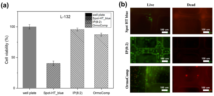
The scaffold was fabricated with the DLP system utilizing three resins together with IP(8:2) as the event materials. L-132 cells, that are regular lung cells, had been cultured on a nicely plate with the three forms of scaffolds. L-132 cells had been seeded in 500 μL at a focus of 5 × 10⁴ cells/cm2. After culturing for twenty-four h, the pattern was handled with 800 μL dimethyl sulfoxide (Sigma-Aldrich). A therapy with 20 μL of MTT (Sigma-Aldrich) was carried out for 4 h. The absorbance was measured at 540 nm utilizing a microplate reader (Asys UVM 340; Biochrom Ltd., Cambridge, UK) to verify cell viability59,60.
A stay/useless cell assay (BioVision, CA, USA) was used to watch cell adhesion and cytotoxicity within the developed supplies. L-132 cells (5 × 10⁴ cells/mL) had been cultured in Spot- HT blue, IP(8:2), and OrmoComp for 3 days. In sequence, cells had been handled with Reside-Dye, a cell-permeable inexperienced fluorescent dye, and propidium iodide, a non-permeable crimson fluorescent dye. The cells had been noticed utilizing a Nikon Eclipse TS100led Trinocular fluorescence microscope (Nikon Company, Tokyo) with a band-pass filter (detect fluorescein and rhodamine), as proven in Fig. 9b.
The cell viability of the resin is proven in Fig. 9a. The cell tradition pictures of Spot-HT, IP(8:2), and OrmoComp resin had been produced utilizing the DLP system. IP (8:2), an isosorbide-based resin, exhibited a excessive cell viability of 95.5%, confirming the biocompatibility of the developed resin. The values of OrmoComp and Spot-HT_blue had been decrease than these of IP(8:2). The setting for cell incubation of IP(8:2) was higher than that of the opposite two constructions. As proven in Fig. 9b, stay and useless staining was carried out to analyze the cell adhesion and cytotoxicity of the developed supplies for 3D cell tradition. The outcomes indicated that the IP(8:2) supplies elevated cell adhesion in comparison with the Spot-HT blue and OrmoComp surfaces. As well as, residing cells had been noticed in cells cultured within the pillars of the IP(8:2) scaffold. No useless cells had been noticed within the IP(8:2) scaffold. This implies that IP(8:2) doesn’t trigger injury to cells, and the fabric is biocompatible. In distinction, the Spot-HT blue scaffold confirmed just a few residing cells, however virtually no hooked up cells in pillars of the scaffold. Moreover, the OrmoComp scaffold had useless cells. Our findings point out that the developed IP(8:2) supplies may be probably used for 3D cell tradition, regeneration, and drug screening in biomedical fields.
[ad_2]
Source_link

