Mechanical power and form accuracy optimization of polyamide FFF elements utilizing gray relational evaluation
[ad_1]
Experiments’ information have been investigated one after the other by evaluation of variance (ANOVA) and Sign-to-noise ratio (S/N). MINITAB® 19.0 was used to research the entire information. Taguchi technique is used to analyze the impact of numerous parameters on a sure response with a fewer variety of experiments.
Multi-response optimization
The GRA technique was concurrently used to optimize multi-response parameters, a statistical technique. This technique concurrently reduces the cylindricity and circularity and will increase the power, elongation, and younger’s modulus by calculating the optimum course of parameters. GRA is utilized within the following steps.
Normalization of experimental information
Step one is to normalize the experimental information. In keeping with the anticipated high quality traits of various responses, this worth might be divided into three standards for optimization in GRA: “larger-is-better,” “smaller-is-better,” and “normal-is-better” are proven in Eqs. (1, 2 and 3) 36.
Bigger-is-better:
$${X}^{*}(p)=frac{{X}_{i}(p)-Min{(X}_{i}(p))}{Max{(X}_{i}(p))-Min{(X}_{i}(p))}$$
(1)
Smaller-is-better:
$${X}^{*}(p)=frac{Min{(X}_{i}(p)){-X}_{i}(p)}{Max{(X}_{i}(p))-Min{(X}_{i}(p))}$$
(2)
Regular-is-better:
$${X}^{*}(p)=1-frac{|{X}_{i}(p)-OB|}{Max{[Max(X}_{i}(p))-OB,OB-Min{(X}_{i}(p))]}$$
(3)
the place X* (p) is the GRG worth, i reveals the variety of trials, Xi(p) represents the response worth of the goal experiment, Max(Xi(p)) is the utmost worth of Xi(p), Min(Xi(p)) demonstrates the minimal worth of Xi(p) and OB is the goal worth. On this research, the “smaller-is-better” is chosen to normalize the cylindricity and circularity, and “larger-is-better” is chosen for power, Younger’s modulus, and deformation the normalized values are proven in Desk 5.
Deviation sequence
The subsequent step is to calculate the deviation sequence from Eq. (4).
$${Delta }_{oi} left(pright)=|| {X}_{0}left(pright)-{X}_{i}left(pright) ||$$
(4)
the place ∆oi (p) represents the deviation sequence and X0(p) is the reference sequence which is the same as one. Values of deviation sequence for every response are given in Desk 636.
Gray relational coefficients
The connection between best and actual regular experimental outcomes is expressed by the Grey Relational Coefficient (GRC). The Gray relationship coefficient is calculated utilizing Eq. (5)36 for every of the normalized values.
$${X}^{*}left(pright)=1-frac{{Delta }_{min}+{zeta .Delta }_{max}}{{Delta }_{oi}left(pright)+{zeta .Delta }_{max}}$$
(5)
the place ζi (p) is Grey Relation Coefficient, ∆oi (p) represents the deviation sequence, ζ is the identification coefficient and has a price between 0 and 1; this coefficient is often thought-about 0.5. Additionally, ∆min and ∆max are minimal and most values of ∆oi (p), respectively. The values are given in Desk 7.
Grey relational grade
Basically, the Grey Relational Grade (GRG) is used to judge the multi-response properties. Alternatively, GRG is the common sum of the GRC, and Eq. (6) is used to find out it36.
$${gamma }_{i}=frac{1}{n}sum_{i=1}^{n}zeta left(pright)$$
(6)
the place n is the variety of prosses parameters. Consequently, a bigger GRG implies that the method parameter mixture is nearer to the best. After that, all experimental experiments have been ranked based mostly on GRG values from 1 to 9, the best GRG worth representing the Optimum run, and it’s thought-about 1st rank. So, the eighth check, which has the best GRG worth, so the eighth experiment has one of the best traits among the many different trials.
Evaluation of GRG information
Evaluation utilizing ANOVA and S/N ratio
Sign-to-noise (S/N) ratio is used to optimize course of parameters and study every parameter’s influence on response. Within the S/N ratio, the “sign” signifies the specified impact, whereas the “noise” signifies the undesirable impact for the responses. Due to this fact, if the S/N ratio is increased, it signifies the optimum circumstances. In keeping with the anticipated high quality traits of various responses, there are several types of S/N ratios, together with larger-is-better, smaller-is-better, and normal-is-better. The place η represents the S/N ratio, yi represents the response worth of the goal experiment within the orthogonal array, yn reveals the variance, and n is the variety of experiments
Bigger-is-better:
$$eta =-10,mathrm{ log}left[frac{1}{n}sum_{i=1}^{n}frac{1}{{y}_{i}^{2}}right]$$
(7)
Smaller-is-better:
$$eta =-10,mathrm{ log}left[frac{1}{n}sum_{i=1}^{n}{y}_{i}^{2}right]$$
(8)
Regular-is-better:
$$eta =-10,mathrm{ log}left[frac{1}{n}sum_{i=1}^{n}{left({y}_{i}-{y}_{n}right)}^{2}right]$$
(9)
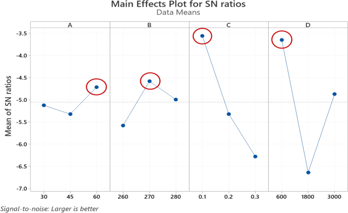
Evaluation of variance (ANOVA) and signal-to-noise ratio (S/N) have been used to research the info obtained from GRG utilizing MINITAB®19.0. To look at the impact of every parameter on GRG, the Taguchi method was utilized. Because of the increased the GRG worth, the specified responses enhance, so “larger-is-better” was used to maximise the GRG to optimize the method parameters. The S/N ratios and response desk of means for GRG are proven in Tables 8 and 9, respectively. These tables present the importance of parameters by using rank, and delta represents the distinction between the best and lowest common. In keeping with the outcomes, it may be stated that the print pace and printing temperature have essentially the most important influence in comparison with the chamber temperature and layer thickness on GRG.
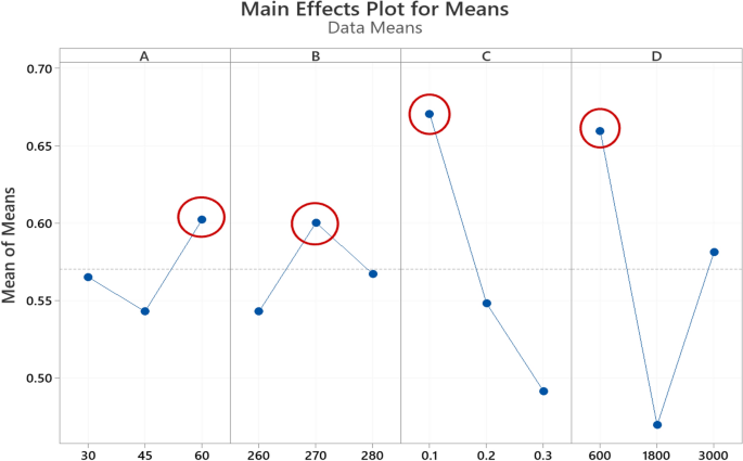
The S/N diagram was used to research the info and decide optimum parameters utilizing common S/N ratios for responses. As minimization of the output, parameters are required for geometrical accuracy (cylindricity and circularity), the “smaller-is-better,” and to maximization of the output parameters are required for mechanical properties (Younger’s modulus, deformation, and power), the “bigger is best” was chosen to maximise mathematical expression for the S/N ratio. The most effective situation is proven by the best level within the S/N ratio graphic. A B, C, and D characterize the chamber temperature, 3D Printing temperature, layer thickness, and print pace in Figs. 9 and 10, respectively. The varied ranges for every parameter are represented on the horizontal axis, and the vertical axis is the imply S/N ratio. In keeping with the Foremost Results Plot for S/N ratio (Fig. 7) and Foremost Results Plot for imply diagrams (Fig. 8), it may be seen that chamber temperature is 60 °C, printing temperature 270 °C, layer thickness 0.1 mm, and print pace 600 mm/min is the optimum mixture of processes parameters for reaching the utmost GRG.
The influence of every course of parameter on the response variables was decided utilizing the ANOVA method. The outcomes of ANOVA are proven in Desk 10. The adjusted sum of squares (Adj SS) was calculated utilizing Eq. (10).
$${s}_{T}=sum_{i=1}^{n}{left({eta }_{i}-{eta }_{j}proper)}^{2}$$
(10)
the place ηi characterize the imply S/N ratio, ηj is the general imply S/N ratio, and n reveals the whole variety of experiments. DF stands for the diploma of freedom, and Contribution is Proportion of contribution of course of parameters, the adjusted imply sum of squares is Adj MS, whereas the variance of the group means and the likelihood worth is F-Worth and P-Worth, respectively. By investigating the F-value talked about in Desk 10 and contemplating that the upper the worth, the larger the impact of the associated parameter, it was decided that print pace, layer thickness, Chamber temperature, and Printing temperature have essentially the most important impact on the quantity of GRG respectively. Contribution Percentages additionally confirms these outcomes.
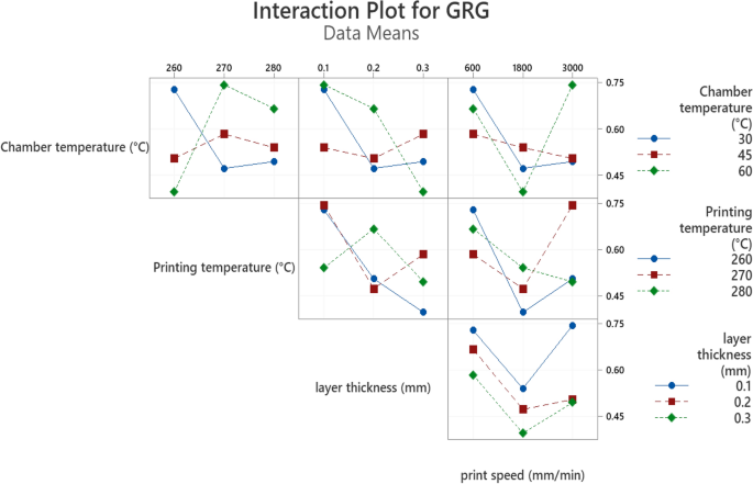
Determine 9, reveals the interplay between course of parameters and GRG values. In an interplay plot, parallel strains indicate no interplay. So in accordance with the determine, in all different diagrams besides pace, there are not any parallel development strains and the instructions are blended. Because of this robust proof that the linear regression mannequin is ineffective for GRG predictions, the response floor technique’s linear-interaction mannequin is used. Utilizing a linear-interaction mannequin of RSM, a multi-objective operate for GRG was constructed and nominal phrases have been faraway from the equation37,38.
Regression modeling of GRG
Response floor regression examines the correlation between variables, which determines the connection between GRG and course of parameters. Additionally, one of the best responses might be achieved by discovering one of the best correlation between components and one of the best ranges of parameters linear-interaction mannequin of the response floor technique is used. The regression mannequin is proven in Eq. (11).
$$GRG=3.38+0.1082A-0.01211 B-28.76C-0.000098D-0.00033A*B-0.071A*C+0.1141B*C$$
(11)
The chamber temperature, printing temperature, layer thickness, and print pace are represented by A, B, C, and D, respectively. The correlation coefficient, typically often known as R-squared, is a statistical software that represents the proportion of variation in a dependent variable and ranges from 0 to one hundred pc. MINITAB 19.0® software program calculates the R-squared worth, and the worth of this coefficient is 99.20 p.c, which signifies a excessive correlation.
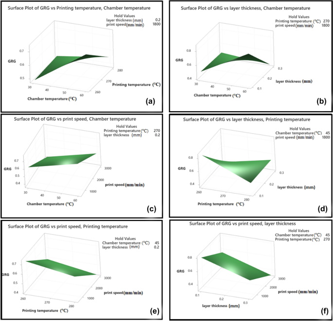
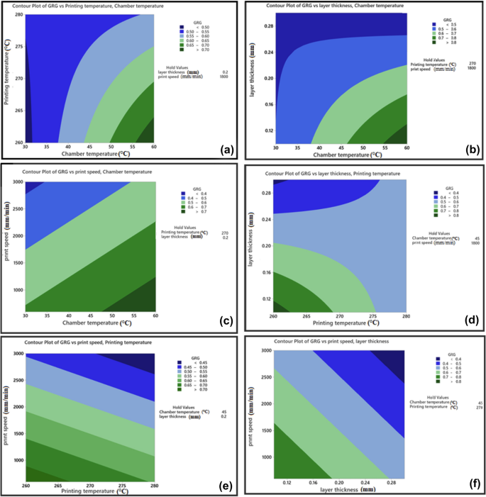
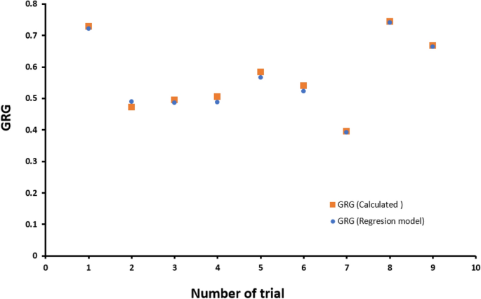
Figures 10 and 11 confer with floor diagrams and contour diagrams, respectively, that are graphical photographs of the regression equation. They present the interactions between two completely different course of parameters on GRG and are made by MINITAB 19.0 software program. As might be seen from these graphs, the best worth of GRG is obtained on the lowest values of layer thickness and print pace and the best values of chamber temperature. Additionally, as is noticed in Fig. 12, by Evaluating the GRG values obtained by the experiments and the GRGs calculated by the regression equation, it’s decided that the utmost error fee is 3%, indicating that the mannequin is validated.
Within the final step, a affirmation experiment was carried out utilizing optimum ranges of course of parameters (Chamber temperature 60 °C, Printing temperature 270 °C, layer thickness 0.1 mm, and print pace 600 mm/min) to confirm this parameter obtained from the GRA and likewise to judge the advance in responses. To make sure repeatability of the outcomes, 5 hole cylindrical elements with optimum parameters have been fabricated by the FFF 3D printer. And the expected Gray relational grade worth or Ypredicted is in comparison with the imply worth of the gray relational grade obtained from the affirmation check. Equation (12) is used to calculate the expected GRG worth for optimum parameters.
$${Y}_{Predicted}={y}_{m}+sum_{i=1}^{n}left({y}_{i}-{y}_{m}proper)$$
(12)
$$Error left({%}proper)=left[frac{{GRG}_{Predicted}-{GRG}_{Experimental}}{{GRG}_{Experimental}}right]*100$$
(13)
$$Improvment left(mathrm{%}proper)=left[{GRG}_{Experimental}-{GRG}_{Intitial}right]*100$$
(14)
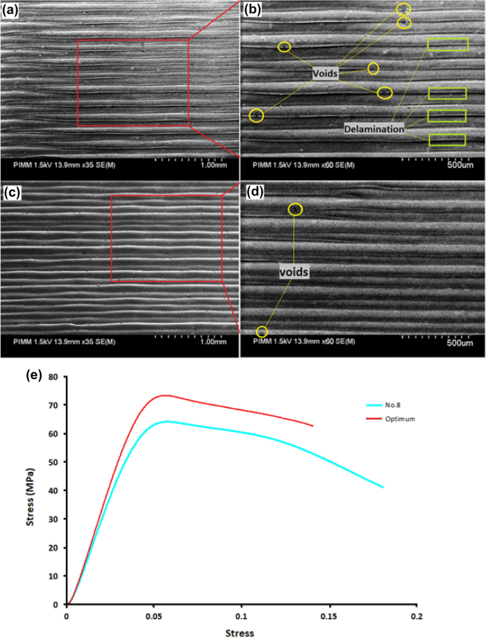
the place ym represents the whole imply of the GRG, yi refers back to the common GRG on the optimum stage, and n is the variety of chosen course of parameters. Then a compression check was utilized to the elements to judge the power, younger’s modulus, and elongation of PA6 elements. Additionally, for measuring geometrical error values akin to cylindricity and circularity, 3D printed elements have been scanned utilizing Solutionix D500, and the measured worth is proven in Desk 11. Additionally, the stress-strain curve of optimum parameters and the eighth trial, which has essentially the most GRG, are in contrast in Fig. 13e. Because it seems, the mechanical properties akin to younger’s modulus and power of the printed half have been improved beneath optimum circumstances. Then, utilizing the values of the obtained responses, the GRG worth for the 3D printed piece with optimum parameters was measured utilizing Eqs. (1), (2), (4), (5), and (6). After calculating the experimental GRG, the subsequent step is to calculate the proportion error between the expected GRG and the experimental GRG. Then the advance in GRG is evaluated. All of the measured values of GRG are proven in Desk 12, and by evaluating the preliminary GRG and the GRG obtained from the experiment and utilizing Eq. (13), it was discovered that the optimum GRG worth has improved by 14%. So, the outcomes present that the values of the optimum parameters obtained from the GRA technique have improved all of the meant responses. Additionally, by evaluating the expected GRG and the GRG of the experiment (Eq. 14), it was discovered that the error fee is the same as 5%. Due to this fact, contemplating this quantity of error, it may be stated that there’s a good correlation between these values.
Determine 13a–d reveals the SEM commentary of the samples manufactured in eighth and optimum circumstances. Extra voids and delamination might be seen within the eighth (preliminary situation) pattern in comparison with the optimum situation 3D printed half. Given the distinction in printing pace for fabrication of those elements, the distinction in print high quality might be attributed to this parameter. One of many important parameters affected by altering the printing pace is thermal gradient39. So, the impact of thermal gradient on delamination between the layers has been emphasised. By growing the nozzle pace cooling fee might be elevated40. So optimum half which printed at a decrease pace might be beneath a decrease thermal gradient than the eighth. So, extra delamination in eighth is justified. Moreover, the weld interface between filaments performs an important position in remaining mechanical properties41. As proven within the Fig. 13 weld interface on this determine, it has not been performed effectively contemplating the presence of some delamination. Few mechanical properties have been anticipated by lowering the weld interface between the 2 filaments. The compression check outcomes present a lower within the compressive power of eighth printed half in comparison with the optimum half. Moreover, the geometric accuracy is much less resulting from extra delamination within the eighth printed half in comparison with the situation 3D printed half42.
The outcomes of this analysis allow the designer to provide high-quality elements. Within the following, the outcomes of this analysis and the optimum choice parameters, and its comparability with different articles expressed within the literature part are mentioned. It was discovered that at 270 °C, the quantity of GRG was optimum. The optimum 3D printing temperature is dependent upon the kind of materials used, and so on., however at low temperatures, the printed layer is sort of strong. The decreased binding power between the layers might be diminished if the brand new layer is deposited. The adhesion might be very poor, so it causes decrease mechanical properties and dimensional accuracy. Alternatively, if the temperature is excessive, the fluidity is simply too excessive, and as a result of gravity power, the soundness of the geometry decreases. It was discovered that the 60 °C chamber temperature, which was the best worth thought-about on this research, is the optimum GRG stage. It is because the excessive chamber temperature will not be too excessive to have an effect on geometric stability. Within the talked about analysis within the literature, it was noticed that the best temperature adopted one of the best dimensional accuracy in PLA elements with growing temperature of 3D printing. One other research on PEEK elements had comparable outcomes to the present work. This may be resulting from completely different supplies used and completely different temperature ranges16,17. Additionally, in a research, the impact of chamber temperature on the power of PEAK elements was investigated. Related outcomes have been noticed19. In keeping with the optimization outcomes, it was discovered that the quantity of GRG at low speeds is increased. As a result of at excessive speeds, the printed layers do not need sufficient time to solidify. The next layers are deposited on the earlier layers, and the piece turns into deformed inside a short while interval. Different PEEK and PC/ABS mix elements analysis indicated that increased printing pace values enhanced and optimized pressure, power, and stiffness. The distinction in outcomes is perhaps resulting from limitations within the cylinder design, the kind of materials utilized, and the responses chosen17,19. The impact of layer thickness as probably the most important parameters in bettering elements’ mechanical properties and accuracy was investigated. It was discovered that the quantity of GRG is increased at decrease layer thickness. A thicker layer thickness ends in increased temperature gradients between the layers, which ends up in extra deformation. Additionally, because the variety of deposited layers will increase, extra interfaces seem, and adhesion reduces. Nevertheless, as indicated within the literature, completely different outcomes and comparable outcomes have been noticed in articles with completely different supplies. And the explanation might be the distinction within the desired responses and the distinction within the chosen materials. Another excuse could possibly be different chosen parameters as a result of all parameters have an effect on one another15,16,19,21.
[ad_2]
Source_link

